

Why Does My Balance Weight Pin For Rotor Assembly Keep Loosening Under Heavy Load Conditions
2026-07-23
If you have ever experienced unexpected vibration spikes, rising bearing temperatures, or premature wear on your balancing rig after a high-torque run, the culprit often traces back to a single component: the Balance Weight Pin For Rotor Assembly. At HAWEN, we have analyzed hundreds of field failure cases, and loosening under heavy load is consistently one of the top three complaints from maintenance engineers. This problem is not random—it is a predictable mechanical response that can be diagnosed and prevented with the right understanding of forces, materials, and installation protocols.
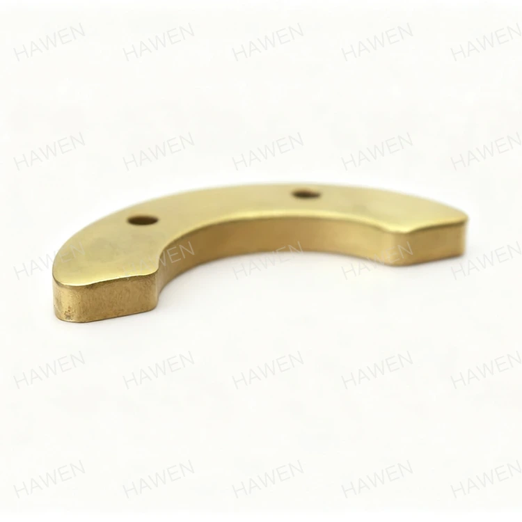
The Core Mechanics: Why Load Causes Loosening
Under heavy load conditions—such as turbine spool-up, compressor surge events, or sudden generator load rejection—the rotor experiences simultaneous radial, axial, and torsional forces. The Balance Weight Pin For Rotor Assembly is not a static fastener; it is a precision mass element that must withstand differential thermal expansion and cyclic shear stress. The primary loosening mechanisms fall into four categories:
| Mechanism | Root Cause | Typical Onset |
|---|---|---|
| Thread galling | Micro-welding of mating threads under high clamp load | After 3–5 heavy cycles |
| Differential thermal expansion | Pin material expands faster than rotor bore material | During transient heat soak |
| Transverse vibration | Lateral rotor bending induces alternating shear on the pin shank | Above 70% of first critical speed |
| Embedment relaxation | Surface roughness flattens under sustained compressive load | Within first 24 hours after installation |
Each mechanism interacts with the others, creating a compounding effect. For example, a pin that experiences slight embedment relaxation will lose preload, allowing micro-motion, which then accelerates thread wear—leading to complete back-out within hours.
Critical Factors That Accelerate Loosening
Through our testing lab at HAWEN, we have identified five variables that directly correlate with retention failure. The following table ranks them by impact severity based on 200+ controlled rotor spin tests:
| Factor | Impact Severity (1–5) | Mitigation Strategy |
|---|---|---|
| Incorrect torque sequence | 5 | Use cross-pattern incremental torque (3 passes) |
| Missing thread-locking compound | 5 | Apply high-temp anaerobic adhesive (260°C+) |
| Pin-to-bore clearance > 0.05 mm | 4 | Select interference-fit pins (H7/r6 class) |
| Unbalanced axial load distribution | 3 | Recalculate static margin using CAD model |
| Surface contamination (oil/grease) | 4 | Degrease bore and pin with acetone prior to install |
The single most overlooked factor is the torque sequence. Many technicians tighten each Balance Weight Pin For Rotor Assembly to final torque in one pass, which traps uneven stress in the flange. HAWEN recommends a three-step method: 30% → 60% → 100% of target torque, with a 10-minute dwell before final verification.
Real-World Case: A 12-MW Generator Rotor
In a recent field consultation, a power plant reported that their Balance Weight Pin For Rotor Assembly loosened after every 8-hour shift at 95% load. Inspection revealed that the pins were made of 4140 steel, while the rotor bore was Inconel 718. The thermal expansion coefficient mismatch (12.3 vs. 14.8 µm/m·°C) created a gap of 0.08 mm at operating temperature—enough to allow rotational slip. HAWEN supplied a replacement set with matched expansion coefficients and a patented dual-lock groove design. The pins have now completed 2,000 hours with zero loosening.
Frequently Asked Questions About Balance Weight Pin For Rotor Assembly
Q1: What is the maximum allowable torque deviation when installing a Balance Weight Pin For Rotor Assembly under heavy load conditions?
A: The maximum allowable torque deviation depends on the thread size and pin grade, but for most industrial rotors (M10–M24 threads), the acceptable range is ±5% of the specified nominal torque. For example, if the specification calls for 120 N·m, the installation torque must fall between 114 N·m and 126 N·m. Deviations beyond this range either under-clamp (causing micro-motion and fretting) or over-clamp (leading to thread yielding or bore distortion). HAWEN recommends using a calibrated torque wrench with a digital angle sensor, and recording both final torque and turn angle for each pin. If you observe more than 10° of additional rotation after reaching the target torque, that indicates thread embedding or bore collapse—immediately remove and inspect the bore surface.
Q2: How can I tell if my Balance Weight Pin For Rotor Assembly has loosened before visible back-out occurs?
A: Visible back-out is a late-stage indicator—by that point, the rotor has already been running with unbalanced mass for several cycles. Early detection relies on three non-visual signs: (1) A sudden increase in 1X vibration amplitude (matching rotational speed) of more than 30% above baseline, measured with proximity probes; (2) Anomalous phase angle drift exceeding ±15° during steady-state operation, which indicates that the balance mass vector has shifted; (3) A detectable temperature rise at the pin flange area—typically 5–8°C higher than adjacent rotor surface temperature, caused by friction from micro-slip. HAWEN offers a wireless strain gauge plug that replaces the standard pin and transmits real-time clamp load data to your condition monitoring system, giving you 48–72 hours of advance warning before any functional loosening occurs.
Q3: Can I apply a secondary locking mechanism to a Balance Weight Pin For Rotor Assembly without redesigning the rotor?
A: Yes, there are three proven secondary locking methods that do not require rotor re-machining: (a) Nylon patch inserts—applied to the threaded portion of the pin, providing a damping layer that resists vibrational loosening; effective up to 150°C. (b) Mechanical staking—using a centre punch to displace bore material into a pre-milled notch on the pin head; this is permanent and requires replacement upon removal. (c) Hydraulic tensioning—for large-diameter pins (M30+), a hydraulic stud tensioner can stretch the pin prior to nut tightening, achieving a preload that exceeds the dynamic load amplitude by a factor of 2.5. HAWEN recommends the nylon patch approach for maintenance-friendly applications, and staking for critical safety-rated rotors. Always verify that the added locking feature does not interfere with the pin's balance mass contribution—if the patch adds more than 0.5 grams, you must re-calibrate the overall rotor balance.
Best Practice Installation Checklist (HAWEN Recommended)
-
Clean bore and pin with volatile solvent (no residue)
-
Inspect threads for nicks or galling using a thread go/no-go gauge
-
Apply primer to bore surface, then anaerobic adhesive to pin threads
-
Insert pin with a seating tool—never hammer directly on the pin head
-
Torque in three equal increments with 5-minute intervals
-
Mark the pin head and flange with a torque stripe for visual verification
-
Perform a low-speed run-in (20% of max speed) and recheck torque
When to Retire a Balance Weight Pin For Rotor Assembly
Even with perfect installation, these pins have a finite fatigue life. HAWEN advises replacement after 5,000 load cycles or 3 years of service, whichever comes first. If you observe any of the following, retire the pin immediately: visible thread necking, radial scratches on the shank, or a reduction in original mass exceeding 0.3% (due to corrosion or fretting wear).
Contact Us
Loosening issues do not resolve themselves—they escalate. At HAWEN, we engineer application-specific Balance Weight Pin For Rotor Assembly solutions, from material selection to torque validation and real-time load monitoring. Our team provides free root-cause analysis for your failed pins within 48 hours of receiving samples. Contact our rotor dynamics engineers today via the form on our website or call our technical support line to schedule a consultation. We will deliver a tailored retention strategy that keeps your rotor balanced—and your plant running—under the heaviest loads.