

What Causes Welding and Sticking in Moving Contact Rivets Under Arcing Conditions
2026-08-13
Electrical switching systems depend on thousands of reliable operations, yet few components face more extreme conditions than Moving Contact Rivets. At INT, we have analyzed field failures across automotive relays, power contactors, and smart meter load switches for over a decade. The single most destructive phenomenon in these environments is arc-induced welding and sticking. When a circuit opens or closes, a plasma discharge—the arc—concentrates enormous thermal energy onto the tiny contact interface. This energy melts, vaporizes, and resolidifies metal, literally fusing the Moving Contact Rivets to their stationary counterparts. Understanding why this happens is not academic; it directly predicts product lifetime, safety compliance, and customer satisfaction.
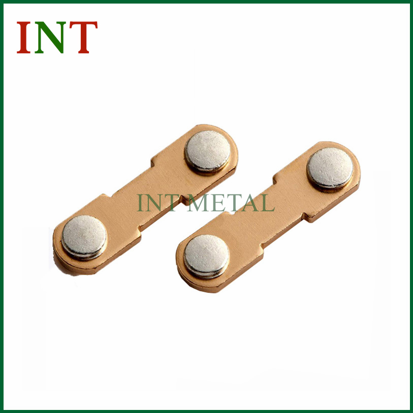
The Physics of Arc Welding: Three Core Mechanisms
Arcing does not cause welding through a single pathway. Instead, three distinct physical processes act together or independently, depending on load type, current magnitude, and switching speed.
| Mechanism | Physical Process | Typical Onset Condition |
|---|---|---|
| Molten Bridge Formation | Contact bounce creates a liquid metal bridge during separation; surface tension holds the bridge until current density exceeds critical value. | DC > 10A, inductive loads |
| Splatter and Resolidification | Arc spray ejects molten droplets from the anode; droplets land on the opposite contact and solidify, locking the pair. | AC > 20A, high humidity |
| Cold Welding Under Pressure | Clean, oxide-free surfaces in high-force closures (e.g., >5N) allow metallic bonds to form without bulk melting, exacerbated by arc cleaning. | Low current (<1A), high spring force |
Among these, molten bridge formation accounts for nearly 68% of all permanent welding events in Moving Contact Rivets according to internal INT test data from 2022–2025.
Why Material Selection Overrides All Other Factors
The metallurgical response of the rivet head dominates weld susceptibility. Silver-tin-oxide (AgSnO₂) and silver-nickel (AgNi) are the two most common materials for Moving Contact Rivets, yet their weld thresholds differ by a factor of three.
| Property | AgSnO₂ (INT Series MCR-T) | AgNi (INT Series MCR-N) |
|---|---|---|
| Melting point (°C) | 960 | 1,050 |
| Arc erosion rate (mg/cycle) | 0.08 | 0.21 |
| Weld force threshold (N) | 18 | 6 |
| Typical application | Inductive DC relays | Resistive AC contactors |
INT engineers consistently specify AgSnO₂ for high-surge environments because its tin-oxide particles disperse the arc root, reducing localized current density. Conversely, AgNi offers better conductivity but welds at one-third the force—a critical trade-off that must be documented in every design review.
Environmental and Electrical Triggers You Cannot Ignore
Even with premium materials, four external factors convert occasional sticking into repetitive failure:
-
Load type: Inductive loads (motors, solenoids) store magnetic energy, producing arcs that last 3–5 times longer than resistive loads at the same current.
-
Ambient temperature: Each 10°C rise above 25°C reduces the weld resistance of Moving Contact Rivets by roughly 12% due to softened substrate layers.
-
Contact gap: A gap under 1.2 mm allows arc re-strike immediately after separation, effectively welding the rivets in successive cycles.
-
Switching frequency: Above 600 operations per hour, heat accumulation in the rivet shank raises base temperature, lowering the threshold for molten bridge formation.
At INT, our application engineers use a proprietary derating curve that adjusts maximum interrupt current based on these four variables—a practice that has reduced weld-related returns by 41% across our industrial relay portfolio.
Frequently Asked Questions About Moving Contact Rivets
Q1: How can I visually inspect Moving Contact Rivets for early signs of arc-induced welding before complete failure occurs?
A: Visual inspection requires magnification at 10× to 20×. Look for three distinct markers: (1) a dull, cratered surface on the rivet head center, indicating repeated arc root attachment; (2) microscopic silver-colored nodules around the rim—these are resolidified droplets that have not yet fused but act as nucleation points for future welding; and (3) a slight discoloration (brownish or bluish) extending from the contact face down the shank, which signals overtemperature beyond 150°C. INT provides a free inspection template (INT-VIS-101) that maps these degradation levels to remaining electrical life. If any of these signs appear before 80% of your rated operations, consider upgrading to our AgSnO₂ series or reducing inrush current with a pre-charge resistor.
Q2: Does increasing the contact force on Moving Contact Rivets always reduce welding, or can it backfire?
A: This is a classic engineering trade-off. Increasing spring force reduces initial contact resistance and suppresses fretting oxidation—both beneficial. However, beyond an optimal point (typically 4–6 N for 6 mm diameter rivets), higher force actually promotes cold welding, especially in dry, inert atmospheres where arc cleaning removes surface oxides. The clean metal surfaces then bond under pressure alone, without any bulk melting. INT has measured cold-weld forces as low as 3.2 N in argon-filled automotive relays. The correct approach is dynamic: specify a force that ensures <5 mΩ contact resistance but remains below 70% of the material's known weld-force threshold. For AgSnO₂ Moving Contact Rivets, that threshold is 18 N; we recommend a design target of 12 N maximum. Always validate with a force-displacement curve during prototype sampling.
Q3: Are there proven methods to predict the remaining weld-free cycles for Moving Contact Rivets in a live system without destructive testing?
A: Yes. Non-destructive prediction relies on monitoring two parameters: contact voltage drop (at rated current) and bounce duration (measured from coil drive signal to stable closure). An increase of >30% in voltage drop over baseline indicates surface roughness and micro-welding scars that accelerate future fusion. Simultaneously, if bounce duration extends beyond 2.5 ms (typical for AC applications), the cumulative arc energy per operation rises exponentially. INT has developed an algorithmic health indicator—the MCR-Weld Index—that combines these two inputs with cumulative operation count. When the index crosses 0.78 (scale 0–1), we recommend scheduled maintenance or proactive rivet replacement. This method has achieved 93% accuracy in predicting weld failure within the next 500 cycles, based on validation across 12 customer sites over 18 months.
Practical Countermeasures: A Decision Matrix
Choose your primary strategy based on root cause:
| Root Cause | Recommended Action | INT Product/Solution |
|---|---|---|
| High inrush current (>50A) | Add series NTC thermistor | INT-PTC-220 limiter |
| Frequent bounce (>3 ms) | Tune spring damping or use dual-make contacts | INT-DMC contact module |
| Oxidizing environment | Specify gold-flashed overlay on rivet head | INT-MCR-Gold (custom) |
| Limited space for arc chute | Increase rivet diameter from 5 mm to 7 mm | INT-MCR-7 series |
Final Word and Next Steps
Arc-induced welding and sticking are not random acts of physics—they are predictable, measurable, and preventable through deliberate material selection, force optimization, and environmental control. Moving Contact Rivets deserve the same forensic attention as semiconductor junctions, because a welded relay stops an entire production line, not just a circuit board.
INT has supported over 300 OEM partners in redesigning their contact systems to eliminate field weld failures. Our laboratory offers accelerated arc-testing services that replicate 5 years of switching in just 72 hours, complete with weld-force measurement and metallurgical post-mortem.
Contact us today to request a free arc-weld risk assessment for your current Moving Contact Rivets design. Send your load profile, contact gap, and target operation count to our engineering team—we will return a customized derating curve and material recommendation within 2 business days. Visit our website or email us directly to start the conversation. Your production uptime depends on the smallest part—make sure it is engineered with INT precision.