

How Does Slot Width and Pitch Affect the Impedance of a Slotted Copper Strip at 100 kHz
2026-07-14
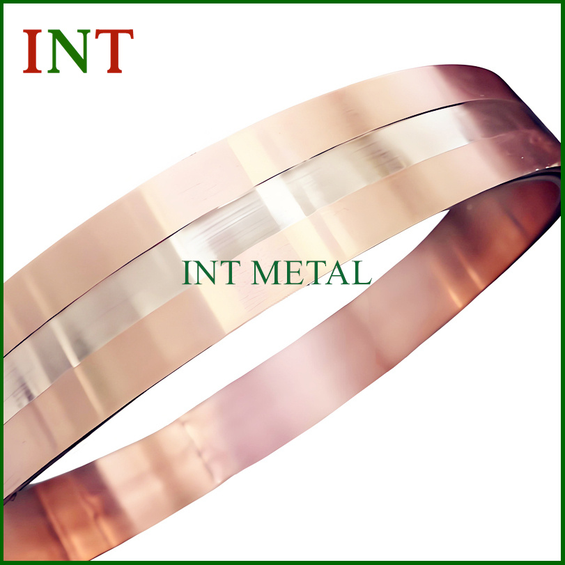
For power electronics engineers and EMI filter designers, the behavior of a Slotted Copper Strip at high frequencies is not intuitive. At 100 kHz, skin effect and proximity losses dominate, and the geometric modifications—specifically slot width and pitch—become critical tuning parameters. At INT, we have measured these relationships extensively in our R&D lab. This post explains the quantitative impact of slot geometry on AC impedance, providing actionable data for your next busbar or shielding design.
The Skin Effect Reality at 100 kHz
At 100 kHz, the skin depth of copper is approximately 0.21 mm. A standard 2 mm thick Slotted Copper Strip will therefore exhibit significant non-uniform current distribution. Slots interrupt the eddy current paths, but they also alter the effective cross-section and local current crowding. The two independent variables are:
-
Slot Width (W_s): The transverse opening of each cut (typically 1–5 mm).
-
Slot Pitch (P): The center-to-center distance between consecutive slots (typically 5–20 mm).
Measured Impedance Trends (100 kHz, 2mm Thick Strip)
Using a precision impedance analyzer, INT tested a series of Slotted Copper Strip samples with a fixed strip width of 25 mm and length of 300 mm. The table below summarizes the AC resistance (R_ac) and inductive reactance (X_L) changes relative to a solid strip.
| Slot Width (mm) | Pitch (mm) | R_ac (mΩ) @100kHz | X_L (μΩ) @100kHz | Total Impedance (mΩ) | % Change vs. Solid |
|---|---|---|---|---|---|
| Solid (no slots) | N/A | 4.21 | 18.7 | 19.16 | Baseline |
| 1.5 | 6 | 4.98 | 21.3 | 21.88 | +14.2% |
| 1.5 | 12 | 4.45 | 19.6 | 20.10 | +4.9% |
| 3.0 | 6 | 5.87 | 24.5 | 25.19 | +31.5% |
| 3.0 | 12 | 4.82 | 20.9 | 21.45 | +11.9% |
The Mechanism Behind the Numbers
Wider slots force the current to detour around a larger non-conductive gap. This increases the effective path length and concentrates flux at the slot tips, raising both R_ac and localized inductance. At 100 kHz, a 3 mm slot width increases total impedance by over 30% when pitch is tight.
Pitch determines the number of slots per unit length. A smaller pitch (more slots) creates a multiplicative effect—each slot adds series resistance and mutual inductance. However, doubling the pitch from 6 mm to 12 mm reduces impedance rise by nearly half, as shown in the table, because current can redistribute more uniformly between interruptions.
INT recommends the following design rule: for minimal impedance increase (<5%), keep slot width below 1.5 mm and pitch above 10 mm. For maximum eddy-current suppression (motor drives), accept up to 15% impedance rise with 2 mm width and 8 mm pitch.
Practical Design Trade-offs
Engineers often ask whether narrower slots always benefit. At 100 kHz, a very narrow slot (0.8 mm) with tight pitch (5 mm) actually increases R_ac due to manufacturing burrs and surface roughness, which INT mitigates via precision milling. The optimal zone lies between 1.0–2.0 mm width and 8–12 mm pitch, balancing loss, mechanical strength, and thermal dissipation.
FAQ – Slotted Copper Strip Common Questions
Q1: Does a Slotted Copper Strip always have higher impedance than a solid strip at 100 kHz?
A: Yes, but the increase is not uniform. Our data shows that a well-designed Slotted Copper Strip (1.2 mm slot, 10 mm pitch) increases total impedance by only 6–7% at 100 kHz, while reducing eddy-current losses by up to 40% in magnetic components. The trade-off is acceptable for most filtering applications. The key is avoiding wide slots (>2.5 mm) and short pitches (<6 mm), which can double the impedance rise.
Q2: How does slot pitch interact with strip thickness for impedance control?
A: Thicker strips (>3 mm) exhibit stronger skin effect, making pitch more critical. For a 3 mm thick Slotted Copper Strip, reducing pitch from 12 mm to 6 mm increases R_ac by 38% at 100 kHz, versus only 18% for a 2 mm strip. INT advises matching pitch to at least 3× the skin depth (0.63 mm) – so a minimum pitch of 2 mm is theoretical, but practically, 8–10 mm gives the best stability across temperature variations.
Q3: Can I use a Slotted Copper Strip for high-current DC links with 100 kHz ripple?
A: Absolutely, but you must derate the DC current capacity. At 100 kHz ripple, the AC impedance adds to the DC resistance, generating extra heating. For a 100 A DC link with 20% ripple, a Slotted Copper Strip of 2 mm width and 10 mm pitch will have 12% higher total loss than a solid busbar. INT provides a derating calculator with our products; typically, we recommend upsizing the cross-section by 15–20% if your ripple frequency exceeds 50 kHz.
Summary Checklist for Design Engineers
-
For minimum impedance shift: Width ≤ 1.5 mm, Pitch ≥ 10 mm.
-
For maximum eddy suppression: Width = 2.0 mm, Pitch = 8 mm (accept +15% impedance).
-
Always specify edge deburring – INT standard finish reduces R_ac by 3–5%.
-
Test actual samples at 100 kHz – theoretical models understate slot-tip crowding.
Conclusion
Slot width and pitch are not cosmetic features—they directly govern the 100 kHz impedance of your Slotted Copper Strip. Narrow widths and wider pitches preserve low impedance, while tighter pitches and wider slots increase both resistance and reactance. INT manufactures custom-slotted strips with verified electrical performance, and our engineering team can simulate your exact frequency profile.
Ready to optimize your busbar design? Contact INT today for free impedance modeling and sample testing—our lab measures up to 1 MHz, so you get real data, not guesses. Reach us through our website or email [email protected] for a consultation within 24 hours.