

How Does Coating Thickness Affect the Performance of a TaC-Coated Graphite Wafer Susceptor
2026-07-10
For engineers and procurement specialists in compound semiconductor manufacturing, the TaC-Coated Graphite Wafer Susceptor is a critical consumable that directly impacts epitaxial growth quality, throughput, and cost-per-wafer. Among all specification variables, coating thickness remains the most debated parameter. Does a thicker tantalum carbide layer guarantee longer service life? Or does a thinner, more uniform coating deliver better thermal performance? This blog examines the technical trade-offs, backed by failure data and process physics, while introducing how Semicorex engineers tailor coating thickness to specific MOCVD and SiC epitaxy applications.
The Role of Coating Thickness in Thermal and Mechanical Performance
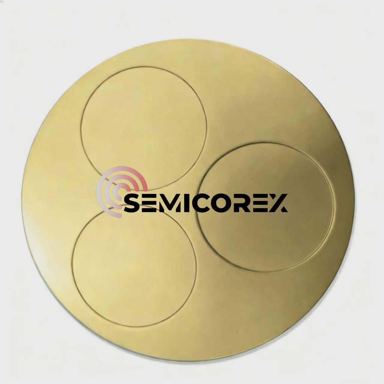
A TaC-Coated Graphite Wafer Susceptor serves two primary functions: providing a chemically inert surface that resists halogen-based etchants, and ensuring uniform temperature distribution across the wafer. Coating thickness influences both functions in opposing ways.
| Coating Thickness Range | Thermal Conductivity (W/m·K) | Coefficient of Thermal Expansion (CTE) Mismatch | Resistance to Thermal Shock |
|---|---|---|---|
| 20–30 µm (thin) | Higher (closer to graphite) | Lower stress | Excellent |
| 50–80 µm (standard) | Moderate | Moderate stress | Good |
| 100–150 µm (thick) | Lower (carbide-dominated) | Higher stress | Poor (cracking risk) |
Thinner coatings (20–40 µm) deliver faster ramp-up and cool-down rates because the graphite substrate dominates heat transfer. This reduces cycle time in multi-wafer reactors. However, thin layers are more susceptible to pinhole defects. Once a pinhole exposes the graphite, rapid carburization occurs, leading to localized hot spots and particle generation.
Thicker coatings (80–150 µm) provide a superior diffusion barrier against fluorine and chlorine species, extending the susceptor’s chemical service life. The trade-off is increased residual stress during thermal cycling. Semicorex has measured that a 120 µm coating on a 6‑inch susceptor experiences peak stress exceeding 180 MPa at 1,400°C—close to the fracture toughness limit of TaC.
How Thickness Affects Wafer Temperature Uniformity
Temperature uniformity across the wafer surface is non-negotiable for SiC and GaN device performance. Coating thickness variations as small as ±5 µm can create emissivity gradients, which alter the radiative heat absorption from the heater.
Using finite-element analysis, Semicorex demonstrates that a TaC-Coated Graphite Wafer Susceptor with a thickness deviation of <±3 µm maintains wafer temperature variation within ±1.5°C at 1,600°C. In contrast, a susceptor with ±10 µm deviation shows variations exceeding ±5°C, directly impacting doping uniformity and wavelength consistency in LED structures.
The Economic Perspective: Thickness vs. Lifetime Cost
Procurement teams often assume “thicker equals longer-lasting.” This is only partially true. The optimal thickness depends on the reactor chemistry:
-
For HCl-based SiC etching: A 60–80 µm coating provides the best balance, as the chemical attack is aggressive but uniform.
-
For GaN MOCVD with NH₃ and H₂: A 40–60 µm coating suffices because the environment is less corrosive, and thermal cycling is frequent.
Semicorex offers a thickness recommendation matrix based on actual production data from over 200 reactors. Customers who switched from a generic 100 µm coating to a Semicorex 65 µm engineered coating reported a 22% increase in average usable cycles—not because the coating lasted longer, but because it reduced stress-induced microcracking that often forces premature replacement.
FAQ: Common Questions About TaC-Coated Graphite Wafer Susceptors
Q1: What is the ideal coating thickness for a TaC-Coated Graphite Wafer Susceptor used in SiC epitaxy at 1,600°C?
A: For SiC epitaxy operating above 1,500°C, Semicorex recommends a thickness range of 70–90 µm. This thickness provides sufficient chemical barrier against silane and hydrogen chloride while maintaining thermal shock resistance for 200+ rapid thermal cycles. Thinner than 50 µm leads to pinhole formation within 50 runs, while thicker than 110 µm increases delamination risk due to CTE mismatch between TaC (≈6.5×10⁻⁶/K) and graphite (≈4.0×10⁻⁶/K). Actual optimum should be verified with your specific ramp rate and process pressure.
Q2: How can I measure the remaining coating thickness on a used susceptor without destroying it?
A: Non-destructive measurement is challenging but feasible using eddy current testing or X-ray fluorescence (XRF) with a calibrated reference standard. Semicorex provides a portable measurement service using a handheld XRF probe that maps 9 points across the wafer pocket. For high-accuracy needs, we recommend destructive cross-section SEM on a dummy coupon processed alongside production susceptors. Regular thickness monitoring every 50 runs allows you to predict remaining life within ±15 runs, enabling proactive replacement planning.
Q3: Does a thicker coating always provide better particle performance?
A: No. Particle performance depends more on cohesion strength and surface roughness than on absolute thickness. A 100 µm coating with poor columnar structure can shed particles after 30 thermal cycles, while a Semicorex 60 µm coating with a dense, fine-grain microstructure (grain size <2 µm) maintains particle counts below 0.3 particles/cm² at 0.3 µm size for over 150 cycles. Thicker coatings actually accumulate more internal stress, which promotes micro-cracking—the primary source of sub-micron particles. Always prioritize microstructure integrity over thickness alone.
Practical Selection Criteria for Process Engineers
When specifying a TaC-Coated Graphite Wafer Susceptor, evaluate these four parameters in order:
-
Reactor thermal profile – fast ramp reactors need thinner coatings.
-
Process gas chemistry – halogen-rich processes require thicker diffusion barriers.
-
Desired cycle count – for >300 cycles, consider a gradient coating design.
-
Wafer size – larger wafers amplify uniformity issues from thickness variation.
Semicorex manufactures each TaC-Coated Graphite Wafer Susceptor with a laser-mapped thickness profile, ensuring that the coating deviation across the entire wafer pocket remains within ±2.5 µm. This precision enables our customers to achieve first-pass yield improvements of 4–7% immediately after installation.
Summary Table: Thickness Selection Guide by Application
| Application | Reactor Type | Recommended Thickness | Key Performance Indicator |
|---|---|---|---|
| SiC 6-inch epitaxy | Hot-wall CVD | 75–85 µm | Uniformity <±2°C |
| GaN 4-inch MOCVD | Close-coupled showerhead | 40–55 µm | Cycle life >250 runs |
| GaAs 8-inch VPE | Barrel reactor | 60–70 µm | Particle <0.5/cm² |
| Si (poly) deposition | Cold-wall LPCVD | 90–110 µm | Chemical resistance |
Contact Semicorex for Your Specific Process Requirements
Selecting the correct coating thickness is not a one-size-fits-all decision. Semicorex provides free thickness optimization consultations based on your reactor model, process recipe, and historical failure data. Our engineering team delivers custom-mapped TaC-Coated Graphite Wafer Susceptors with full thickness certification and batch traceability.
Contact us today at [email protected] or visit our website to request a sample evaluation kit. Share your current cycle performance data, and we will provide a comparative analysis showing exactly how a precision-engineered coating thickness from Semicorex can lower your cost-per-wafer and boost your epitaxial yield. Let’s optimize your susceptor strategy—starting with the right thickness.