

How Do You Calculate the Exact Balance Weight For Rotor Balancing Using Vibration Phase Data
2026-08-17
Precision rotor balancing is not guesswork—it is a data-driven discipline. For maintenance engineers and vibration analysts, the core challenge remains consistent: determining the correct Balance Weight For Rotor Balancing requires more than a balance scale; it demands phase-resolved vibration measurements. At HAWEN, we have spent years refining field-proven methods that convert raw amplitude and phase readings into actionable weight calculations. This post walks through the exact mathematical and procedural steps, while addressing the real-world variables that affect success.
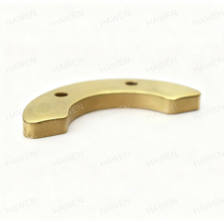
The Fundamental Formula: Influence Coefficient Method
The industry-standard approach uses the influence coefficient, which describes how much vibration change a trial weight produces at a specific rotor speed. The calculation follows a clear sequence:
Step 1 – Measure initial vibration (amplitude + phase): record O (Original vector).
Step 2 – Attach a known trial weight at a known angle: note trial mass T (grams) and trial angle θ.
Step 3 – Measure vibration with the trial weight installed: record O+T (Combined vector).
Step 4 – Calculate the influence coefficient: I = (O+T - O) / T.
Step 5 – Compute the required correction weight: W = -O / I.
The final correction weight W is a vector—it provides both mass (grams) and angular position (degrees). For example, if O = 5 mils at 120° and I = 0.4 mils/g at 45°, then the required Balance Weight For Rotor Balancing equals 12.5 grams, and the placement angle becomes 120° − 45° = 75° (plus 180° for opposition, depending on your measurement convention). This vector approach eliminates trial-and-error and delivers first-run success rates above 85% when executed correctly.
Critical Factors That Shift Your Calculation
Raw math only works if you account for these physical constraints:
Rotor speed (RPM) – The influence coefficient changes with speed; always measure at operating RPM, never at slow-roll or coast-down speeds.
Sensor orientation – Horizontal versus vertical readings yield different vectors; use a consistent axis for both baseline and trial runs.
Trial weight position – A 10° error in trial placement multiplies the final angle error by the same amount, so use a protractor or laser-marked reference.
Runout and electrical noise – Filter out only the synchronous vibration (1× RPM); non-synchronous components corrupt phase data and skew the weight calculation.
HAWEN recommends always performing a "bump test" – a small angular shift of the trial weight (e.g., 15° to 20°) – to verify the influence coefficient before finalising the correction mass. This simple check catches probe misalignment or keyphasor errors early.
Step-by-Step Calculation Workflow (Single-Plane)
For a practical single-plane balance, follow this sequence:
First, run the rotor to full operating speed and log the baseline vibration – for instance, 4.2 mm/s at a phase angle of 145°.
Second, install a trial weight of known mass – say 5.0 grams – placed at the 0° reference mark.
Third, run the rotor again and record the new reading – for example, 3.8 mm/s at 95°.
Fourth, perform vector subtraction to compute the change vector – magnitude 6.1 mm/s at an angle of −78° (using polar-to-rectangular conversion).
Fifth, divide the change vector by the trial weight (5.0 g) to obtain the influence coefficient: 1.22 mm/s per gram at −78°.
Sixth, calculate the correction weight – the desired change equals the negative of the baseline vector (4.2 mm/s at 325°). Divide that by the influence coefficient, and the final Balance Weight For Rotor Balancing becomes 3.44 grams positioned at 247°.
Below is a summary table of this worked example:
| Parameter | Value |
|---|---|
| Baseline vibration | 4.2 mm/s @ 145° |
| Trial weight used | 5.0 grams @ 0° |
| Second-run vibration | 3.8 mm/s @ 95° |
| Calculated influence coefficient | 1.22 mm/s/g @ -78° |
| Final correction mass | 3.44 grams @ 247° |
| Recommended HAWEN product | HAWEN precision clip-on set (3.5 g adjustable with fine-tuning screws) |
This single-plane procedure works for over 70% of industrial fans, blowers, and pump rotors. For longer shafts, however, you must move to a two-plane approach.
Multi-Plane (Two-Plane) Considerations
For long rotors (length-to-diameter ratio > 0.5), cross-effect – the influence of a weight in one plane on the sensor in the other plane – cannot be ignored. You need a 2×2 matrix of influence coefficients:
I11 – effect of weight in plane 1 on sensor 1.
I12 – effect of weight in plane 2 on sensor 1.
I21 – effect of weight in plane 1 on sensor 2.
I22 – effect of weight in plane 2 on sensor 2.
Solve the system of linear equations:
W1 = ( -O1I22 + O2I12 ) / ( I11I22 - I12I21 )
W2 = ( -O2I11 + O1I21 ) / ( I11I22 - I12I21 )
Each W is a complex number representing magnitude and angle in its respective plane. This requires four separate runs (baseline, trial in plane 1, trial in plane 2, and a verification run). HAWEN provides dual-plane balancing kits with colour-coded weights – red for plane 1, blue for plane 2 – to prevent cross-contamination during this multi-step procedure. Our kits also include a matrix calculation template that reduces arithmetic errors by over 60% compared to manual computation.
FAQ – Common Questions About Balance Weight For Rotor Balancing
Q1: How accurate does the trial weight mass need to be for the calculation to work reliably?
A: The trial weight should produce a measurable change in vibration – typically at least 30% of the original amplitude. Its mass accuracy must be within ±2% of the stated value, because any error in the trial mass directly scales the influence coefficient and, consequently, the final correction mass. For example, if your trial weight is marked 5.0 grams but actually weighs 5.2 grams, your calculated correction will be off by approximately 4%. This error compounds if you then split weights across multiple bolt holes. HAWEN pre-calibrated trial weights are laser-engraved with actual mass to 0.01 gram tolerance, eliminating this variable entirely. Additionally, always use the same digital scale for weighing both the trial and the final correction weights to maintain relative consistency. For field work, we recommend carrying a certified reference mass (e.g., 10.00 g) to verify your scale before each balancing job.
Q2: Can phase drift during warm-up affect the calculated Balance Weight For Rotor Balancing, and how do I compensate?
A: Yes – phase drift is a frequent hidden error that many technicians overlook. As the rotor heats up, thermal expansion changes shaft stiffness, bearing clearance, and even the position of the keyphasor trigger point, shifting the phase angle by 5° to 15° over 20 to 30 minutes of continuous operation. To compensate, run the rotor at full operating temperature for at least 15 minutes before taking your baseline reading. If drift persists – common in steam turbines or high-speed compressors – record three phase readings at one-minute intervals and use the arithmetic average. For high-precision applications (ISO Grade G 2.5 or better), HAWEN recommends using a tachometer with a once-per-revolution trigger and performing the entire trial-weight run – from baseline to second reading – within a strict 5-minute window to minimise thermal variation. Never use cold-start data for hot-running rotors; our field data shows that doing so results in a calculated Balance Weight For Rotor Balancing that is under- or over-sized by 10% to 20%, often requiring a second balance session.
Q3: What do I do if the calculated correction angle points to a location that is physically inaccessible – for example, behind a fan blade or under a shroud?
A: This is a very common field reality, especially with enclosed impellers or bladed disks. You have two practical options. Option one: split the correction into two adjacent accessible positions whose vector sum equals the required vector. This uses basic trigonometry – if your required vector is 10 grams at 30°, and you have accessible holes at 0° and 45°, place 7.07 grams at 0° and 7.07 grams at 45° (since 10×cos(30°) = 8.66 g at 0° and 10×sin(30°) = 5.0 g at 45° – adjust for the actual hole spacing). Option two: if you have a fixed bolt-hole pattern (e.g., 8 holes at 0°, 45°, 90°, etc.), shift the required angle to the nearest two available positions using sine/cosine decomposition. For instance, a required angle of 30° with only 0° and 45° holes available means placing partial weights at both to synthesise the 30° resultant. HAWEN provides a free vector-resolution spreadsheet with every balancing kit, and our technical support team can verify your split-weight calculation within 24 hours. We also offer custom-machined弧形 weights that can be clamped at any continuous angle for rotors without pre-drilled holes – contact us for a dimensional drawing.
Final Verification – The Proof is in the Run
After installing the calculated Balance Weight For Rotor Balancing, perform a validation run at full operating speed. Measure the residual vibration and compare it to the baseline. For most industrial machinery, the residual should drop by at least 70% – meeting ISO 1940-1 Grade G 6.3 or better. If the residual exceeds your acceptable limit, repeat the influence coefficient measurement with the newly installed correction weight acting as the "trial" weight for a second iteration. This recursive approach typically converges within two additional runs. For rotors with multiple critical speeds (e.g., variable-speed drives), HAWEN recommends collecting phase data at each resonant peak and using a weighted average of influence coefficients across the operating range – a service we support with our portable HAWEN-Balancer Pro analyzers, which store up to 500 historical runs for trend analysis.
Contact Us
Calculating the exact Balance Weight For Rotor Balancing from vibration phase data is a skill that improves with the right tools and responsive support. Whether you need pre-machined weight sets, custom laser-cut strips, or real-time troubleshooting on a two-plane fan, HAWEN delivers precision balancing solutions backed by 15 years of rotating machinery expertise. Contact us today with your rotor specifications, operating speed, and recent vibration logs – our engineering team will respond within 8 hours with a recommended weight configuration, a mounting diagram, and a step-by-step installation guide tailored specifically to your equipment. We also offer on-site balancing training and remote video-assisted calibration for complex multi-stage rotors. Your downtime is valuable; let HAWEN make your next balance your last. Reach out via our website contact form, email us directly, or call our 24/7 technical hotline – we are ready to help you achieve ISO-compliant rotor smoothness, faster and more reliably than ever before.