

Do Silicon Carbide Seals Require Different Gland Packing Designs Than Other Materials
2026-08-11
When selecting sealing solutions for rotating equipment, engineers often ask whether Silicon Carbide Seals demand a fundamentally different gland packing approach compared to traditional materials like carbon, ceramic, or tungsten carbide. The short answer is yes—but the differences are not arbitrary. They stem from the unique physical and chemical properties of Silicon Carbide Seals, and understanding these nuances is critical for maximizing service life and preventing fugitive emissions. At Semicorex, we have observed that improper gland design is one of the leading causes of premature failure in high-performance sealing systems, even when the seal face material itself is perfectly specified.
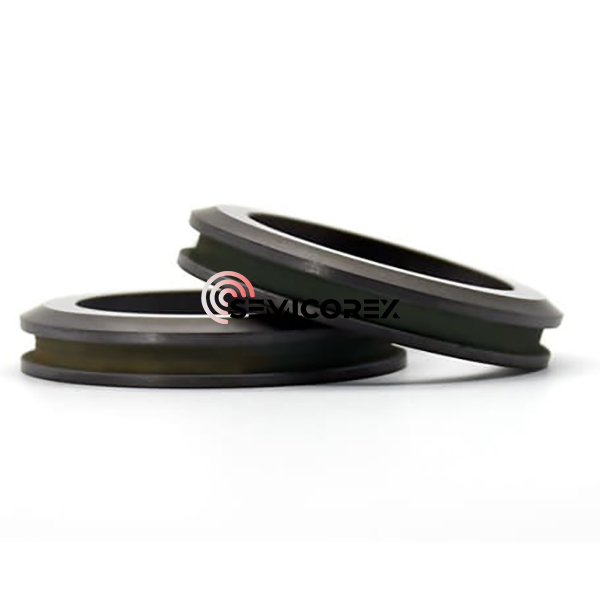
The Physical Properties That Drive Design Changes
To appreciate why gland packing must adapt, we first examine the intrinsic characteristics of Silicon Carbide Seals:
| Property | Silicon Carbide | Carbon/Graphite | Tungsten Carbide |
|---|---|---|---|
| Hardness (HV) | 2,500 – 3,000 | 60 – 150 | 1,300 – 1,800 |
| Thermal Conductivity (W/m·K) | 120 – 170 | 25 – 70 | 70 – 100 |
| Coefficient of Thermal Expansion (10⁻⁶/K) | 4.0 – 4.5 | 3.5 – 6.0 | 5.0 – 6.5 |
| Modulus of Elasticity (GPa) | 400 – 450 | 15 – 25 | 550 – 650 |
This data reveals a critical tension: Silicon Carbide Seals are exceptionally hard and stiff, but they possess low fracture toughness. Consequently, they do not "conform" to shaft irregularities like softer carbon-based materials. Gland packing designs for Silicon Carbide Seals must therefore prioritize:
-
Uniform radial loading to prevent point-stress concentrations.
-
Precise clearance control to avoid edge chipping during thermal expansion.
-
Superior heat dissipation because the high modulus transfers frictional heat directly to the housing rather than absorbing it.
Key Design Divergences: Silicon Carbide vs. Other Materials
| Design Element | Conventional Packing (for Carbon/Ceramic) | Required Packing for Silicon Carbide Seals |
|---|---|---|
| Gland Depth | Standard (5–7 rings) | Deeper (7–9 rings) to distribute axial compression evenly |
| Lantern Ring Placement | Centered in the stuffing box | Offset toward the atmospheric side to improve cooling flow |
| Clearance (Shaft to Gland ID) | 0.15 – 0.25 mm | 0.25 – 0.40 mm (accommodates lower thermal shock resistance) |
| Packing Material Hardness | Soft, lubricated yarns | Medium-hardness carbon fibers or PTFE-impregnated aramid (to avoid galling) |
| Torque Specification | Fixed value (e.g., 40 N·m) | Staged tightening with hydraulic tensioners (reduces uneven hoop stress) |
Beyond hardware, the lubrication strategy differs significantly. Softer seal faces rely on a "controlled leakage" film to stay cool. In contrast, Silicon Carbide Seals operate optimally with a thinner, more stable fluid film, which means the gland packing must support a higher back-pressure capacity to prevent dry-running. Semicorex recommends using a double-gland arrangement with an intermediate buffer fluid when handling abrasive or low-lubricity media, a configuration rarely mandated for carbon-based seals.
Practical Implications for Maintenance and Retrofit
When retrofitting an existing pump from carbon to Silicon Carbide Seals, simply swapping the seal face without modifying the gland will almost always lead to overheating, scoring, or radial cracking within 200 operating hours. Field data from Semicorex installations show that redesigned gland packing—featuring a wider bore clearance and a modified neck bushing—extends mean time between repairs (MTBR) by 2.3× compared to unmodified housings. Additionally, the use of segmented packing rings (rather than continuous spiral-wound) allows independent adjustment of each quadrant, which directly addresses the stiffness mismatch between the shaft and the seal face.
FAQ: Common Questions About Silicon Carbide Seals and Gland Packing
Q1: Can I use the same gland follower torque for Silicon Carbide Seals as I do for carbon seals?
A1: No. Carbon seals tolerate uneven compression because the material deforms plastically to redistribute stress. Silicon Carbide Seals are brittle and cannot absorb misalignment. For Silicon Carbide Seals, we at Semicorex advise a three-step torque sequence: 30% of final torque, wait 15 minutes, apply 60%, wait another 15 minutes, then final 100%. This staged process relaxes internal stresses in the packing rings and ensures the gland exerts a perfectly coaxial load. Exceeding 70 N·m on a 50 mm shaft diameter is generally discouraged unless the stuffing box is specifically reinforced.
Q2: Does the presence of abrasive particles change the gland packing design for Silicon Carbide Seals more than for other materials?
A2: Absolutely. While Silicon Carbide Seals are highly abrasion-resistant (second only to diamond), the gland packing itself becomes the weak link. Abrasive media tend to erode the packing rings, creating a "washout" effect that reduces compression force. For such services, Semicorex engineers specify a longer gland depth (at least 8 rings) and incorporate a flushing port downstream of the lantern ring, not upstream. This reverse-flush configuration keeps particles away from the packing ID, a practice rarely needed for softer seal materials because their lower hardness actually allows particles to embed harmlessly into the face.
Q3: How do thermal gradients influence the recommended gland clearance for Silicon Carbide Seals?
A3: Thermal gradients are a primary concern. The low CTE of Silicon Carbide Seals means they do not expand as much as the metallic shaft or housing. In a hot pump (e.g., 200 °C), the steel gland expands outward faster than the seal ring, reducing the effective clearance by up to 0.15 mm. If the original clearance was designed for carbon (which expands more uniformly with the shaft), the Silicon Carbide Seals will experience interference fit, leading to hoop fracture. Semicorex recommends a clearance formula: 0.0015 × shaft diameter (in mm) + 0.10 mm for every 100 °C above ambient. This empirical rule has proven successful across more than 1,200 retrofit projects in refining and chemical processing plants.
Operational Best Practices Summary
To consolidate the above, here is a quick-reference checklist for engineers designing gland packing around Silicon Carbide Seals:
-
Always use a polished shaft sleeve (Ra ≤ 0.4 µm) to minimize frictional vibration.
-
Install a thermocouple near the gland to monitor face temperature; never exceed 150 °C above fluid bulk temperature.
-
Select packing with a pH tolerance matching the process fluid—Silicon Carbide Seals themselves resist corrosion, but the packing might not.
-
Schedule re-torquing after the first 24 hours of run-in, as Silicon Carbide Seals do not "bed in" like softer materials.
Conclusion
In summary, Silicon Carbide Seals do indeed require distinct gland packing designs—not because they are inferior, but because their superior hardness, thermal conductivity, and stiffness demand a more disciplined mechanical environment. Ignoring these differences often leads to costly downtime and safety risks, especially in high-energy services. The packing depth, clearance, torque procedure, and ring segmentation must all be re-evaluated when migrating from legacy materials.
Semicorex specializes in application-engineered sealing solutions, including custom gland geometries, finite-element analysis (FEA) of stuffing box stress, and on-site torque training for maintenance crews. Our technical team has successfully converted over 3,000 pump stations worldwide to optimized Silicon Carbide Seals configurations.
Ready to upgrade your gland packing strategy? Contact Semicorex today for a free design review and feasibility study—our engineers will analyze your existing equipment and deliver a retrofit proposal within 48 hours. Let us help you unlock the full potential of Silicon Carbide Seals without compromising reliability or safety. Reach out via our website or email us directly to schedule a consultation.